

Metal Injection Molding (MIM) is one of the most efficient technologies for producing small and complex metal components with high precision. At MimecriUSA, we specialize in custom MIM parts manufactured in the USA, supporting sectors like automotive, defense, aerospace, and medical. Our experience shows that good design is critical to ensure functional performance, dimensional reliability, and cost efficiency.
This article outlines the essential design rules engineers and manufacturers should follow to get the most out of the MIM process.
What Is MIM and how does it work?
MIM combines the versatility of plastic injection molding with the strength of sintered metal. The process starts with a feedstock, metal powder mixed with a binder, that is injected into a mold to create a “green” part. After the binder is removed in a controlled debinding phase, the part undergoes sintering, where metal particles fuse together, achieving up to 98% of full density. The result: a high-performance part with tight tolerances and excellent surface finish, often with no need for post-machining.
We have published a detailed article that explains each step of the MIM process, from feedstock preparation to final sintering, using a metal part as a reference model.
Advantages and Limitations of MIM
The advantages of MIM include:
- Excellent geometric accuracy and dimensional repeatability
- Superior surface finish, often Ra < 1.6 µm
- Design freedom, enabling internal features, thin walls, and complex geometries
- Reduction or elimination of machining, which saves time and cost
However, MIM has some limitations:
- It’s most cost-effective for medium to high production volumes (typically 5,000+ units/year)
- Initial mold costs can be significant
- Part weight is generally limited to <100g for best performance-cost balance
That’s why smart design, aligned with process capabilities, is essential to maximize MIM’s advantages.
Design guidelines for MIM parts
The optimal MIM part could be defined:
- Length less than 100 mm
- Ratio length/width must be less than 5
- Weight can vary between 0.5 and 50 grams
- Wall thickness: between a range of 0.5 and 15 mm
Currently, dimensional tolerances are governed by an ISO 2768 standard, although the Ecrimesa Group can offer for some dimensions a better range than the standard. It is necessary, in any case, to analyze this situation for each part.
Tolerance table
| DIMENSION (mm) | ECRIMESA | EPMA (ISO 2768) | INVESTMENT CASTING (D2 P690:2010) |
|---|---|---|---|
| <1.5 | ±0.03 | ||
| <3 | ±0.04 | ±0.05 | ±0.12 |
| 3-6 | ±0.05 | ±0.06 | ±0.12 |
| 6-9 | ±0.06 | ±0.075 | ±0.14 |
| 9-12 | ±0.07 | ±0.075 | ±0.17 |
| 12-15 | ±0.08 | ±0.075 | ±0.17 |
| 15-20 | ±0.10 | ±0.15 | ±0.17 |
| 20-25 | ±0.12 | ±0.15 | ±0.20 |
| 25-30 | ±0.15 | ±0.15 | ±0.20 |
| 30-45 | ±0.18 | ±0.25 | ±0.30 |
| 45-60 | ±0.24 | ±0.25 | ±0.30 |
| >60 | ±0.5% | ±0.4% |
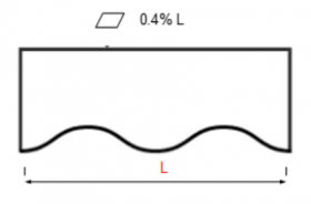
When designing a part for MIM, several dimensional parameters are key to ensuring optimal performance and cost-efficiency. At MimecriUSA, we typically work with parts up to 150 mm in length, maintaining a length-to-width ratio below 5 to guarantee dimensional stability. Ideal part weights range from 0.5 to 50 grams, although we are able to manufacture components up to 200 grams when justified by significant machining savings. For best results, wall thicknesses should not drop below 0.4 mm, and internal radii should be at least 0.2 mm to facilitate material flow and reduce stress concentrations. We achieve surface roughness values under Ra 1.6 µm, and flatness is controlled to within 0.4% of the maximum flat surface dimension, ensuring reliable sintering support and part consistency.
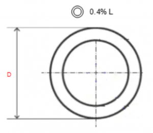
Alignment and concentricity can be maintained within a minimum of 0.1 mm or 0.4% of the maximum dimension.
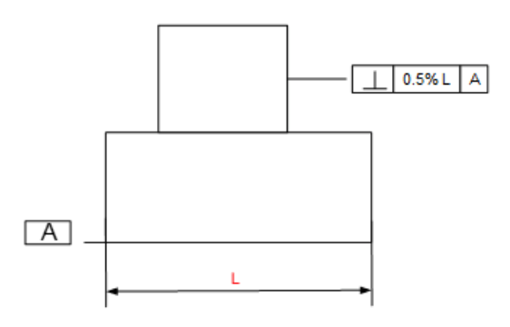
Perpendicularity can be guaranteed within 0.1 mm or 0.5%, depending on part geometry.
Design rules for MIM parts step by step
To ensure a reliable process and cost-effective production, it’s essential to follow specific design rules tailored to Metal Injection Molding (MIM). These principles not only improve manufacturability and part quality but also help reduce overall production costs.
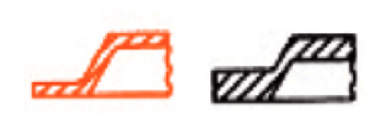
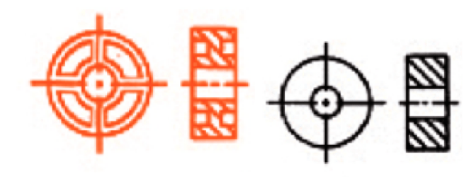
1. Maintain uniform wall thicknesses, or at least ensure smooth transitions between sections, to prevent issues like shrinkage, warping, or cracking.
2. Avoid unnecessary mass or oversized features that don’t contribute functionally—this helps improve dimensional control and reduces raw material use.
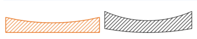
3. Incorporate flat surfaces on one side of the part to provide stability during debinding and sintering, avoiding deformation and eliminating the need for custom supports.
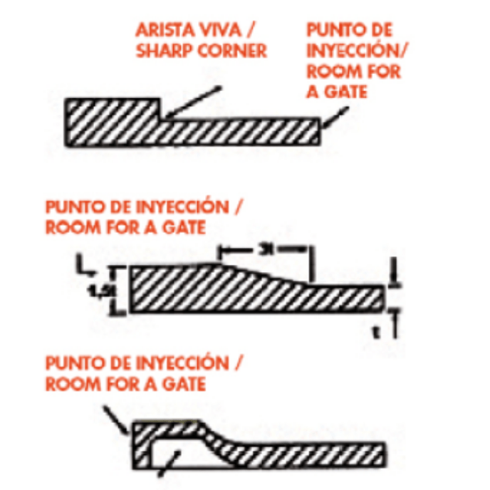
4. Minimize stress zones by using generous internal and external radii—anything above 0.2 mm helps the material flow better during injection and reduces defect risks.
5. Identify a specific, non-functional area for the injection point, as it may leave a small mark. If acceptable, this reduces the need for post-processing.
6. Define non-critical areas for both the parting line and ejector pin locations.
7. Add draft angles to assist in part ejection from the mold and prevent surface damage.
8. For external threads, design lateral planes to allow clean mold separation. Internal threads are possible, but due to the high tooling cost, they’re best avoided unless absolutely necessary.
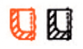
9. Design bores with care—their diameter should be smaller than the surrounding wall thickness, and their depth should not exceed five times that thickness.
10. Functional or aesthetic details such as numbers, logos, and part codes can be incorporated directly into the mold, eliminating secondary marking operations.
Reducing MIM costs through smarter part design
The cost of a MIM part is primarily driven by two key factors: the material selected and the geometry of the part. Stainless steels, for example, are significantly more expensive than low alloy steels—not only due to raw material price, but also because they require slower sintering cycles in hydrogen atmospheres. Learn more about how design and material choices impact pricing in our detailed article: What determines the cost of a MIM part?
Set Your MIM project up for success
Designing for Metal Injection Molding is more than just meeting technical requirements, it’s about making smart decisions early that lead to better performance and lower costs. By applying the right design principles, you not only reduce complexity but also improve overall manufacturing efficiency.
At MimecriUSA, we combine the proven expertise of Ecrimesa Group with the responsiveness and reliability of a trusted U.S.-based manufacturing partner. From prototyping to full production, our facility in Georgia is ready to support your next project with speed, precision, and technical know-how.
Ready to take the next step? Get a quote and let our team help you bring your custom MIM part to life.


